frameBuilder  : Analyzes 2D/3D structure of members and
plates.

Click ▶ for more information... ▼ to contract...
TagNAct: Tag (Select) structural elements then Act on them
TagNAct works in real time graphics and is WYSIWYG (What You See
Is What You Get). It means that the outcome of the TagNAct action is displayed right in front of you. If it is not desirable, click the Undo  button to
reverse the action. In our system TagNAct performs model and loading definitions.
How to Tag (Select): Left click a joint, or any point on the line of a member, or the centroid of a plate to tag it. Once tagged, the color is red. You may tag multiple elements by their common attributes.
How to Act: Once elements are tagged, right click, and a list of available actions is displayed.
Select the desired one, fill in the corresponding parameters, execute the action. The intended action (either geometry or loading) will be executed on the tagged elements and the screen is refreshed accordingly.
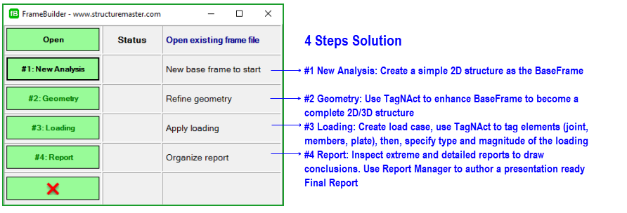
#1 Start a new Analysis: Create a BaseFrame
Every model starts from a simple 2D sketch - a BaseFrame. Here is a picture of 6 BaseFrames and their target structures. Take a look at these 6 BaseFrames and their final model configurations to get an idea of how to build a complete structrue. Among these 6 examples, the first 5 BaseFrames are rectangular grids in the XY plane. Because most of the structures are rectangular shaped, Only case #6 provides the sample circular BaseFrame in the XZ plane.
Building a BaseFrame is a 3 step guided task. frameBuilder asks: 1) Is this a 2D or 3D analysis? 2) Is this structure rectangular, circular, or elliptical? and 3) What are the key coordinates of the BaseFrame.
Among the 6 examples, cases #1 and #2 are 2D frames. Their BaseFrames are rectangular grids in the XY plane. For them, the answer to questions 1) and 2) are obvious. For question 3), you may provide a few key X and Y coordinates to define the XY BaseFrame grid. Next step is to enter '#2: Geometry' to enhance this BaseFrame to become a completely defined 2D model.
For the 3D cases among cases #3, #4, and #5, their BaseFrame is the typical plane on the XY plane of the 3D model. After the key coordinates of the XY BaseFrame are defined, enter '#2: Geometry' to enhance it to complete the definition of the typical frame. Once done, we can duplicate this typical frame to different locations and put the finishing TagNAct touches on them to complete the definition of the 3D model.
Build a 3D model from a simple 2D sketch
Use common sense to define a BaseFrame. With the help of our powerful TagNAct, no matter what BaseFrame you choose, you will always complete your model building with minimum difference in the time spent.
#2 Geometry: Enhance BaseFrame to completed model
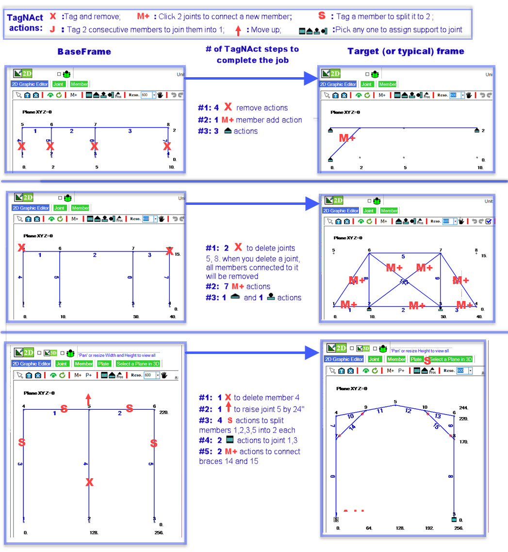
After the BaseFrame is done, the next step is to define model geometry. TagNAct’s geometry actions are: Add New, Connect, Duplicate, Remove, Move, Merge, Spilt, Join, Cut, Assign Support, Add Grid, Add Plates. The bold faced actions are the ones used in the below 2 sets of examples:
Examples of
enhancing 2D models.
Examples of
enhancing 3D models via duplication.
Most of the time, our extensive TagNAct actions empower you to complete your model definition in less than 20 minutes.
#3 Loading: Create load cases and apply loadings
frameBuilder uses Loading Manager to manage load cases and combinations.
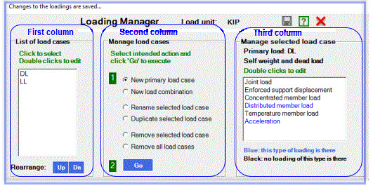
Each load case has a unique tag (load case name). Once a load case is created, you may use TagNAct to add loadings to it. First, tag the loaded elements and then, select the desired type of loadings among: 1) joint loads, 2) enforced support displacement loads, 3) concentrated member loads, 4) distributed member load, 5) temperature member loads, and 6) acceleration loads (self weighted).
This is the
Loading Manager dialog box.
Next is the
Display of member and joint loads of load case WINDX of analysis DuctCover. Please take a look at our User's manual: frameBuilder\Sample problems\2DF_08J_DuctCover. DuctCover is a structure of simple geometry but with extensive 4 primary and 3 load combinations. It provides excellent instructions on how to organize and define loadings.
#4 Report: Authorize a presentation ready Final Report
Extreme and Detailed Report: Once the model is built, loadings defined, the #4 Report presents a 2 parts report. The first part reports the extreme values of the selected load cases. It gives you an overall view of the analysis. The second part is the detailed output of each load case. Depending on the complexity of the model and number of the load cases, the second part can be hundreds or even thousands of pages. If you want to take a look at the details, we provide “Text Report Viewer”. This App has a TOC so that you may navigate and investigate through details
(Video) to draw conclusions.
Summary Report: After you’ve reviewed the Extreme and Detailed Report, it’s time to draw conclusions. For that, we have a Summary Report Template. Simply provide information to a few questions (questions are: Owner, Objective, Geometry, Loadings, Conclusion, and Performed by) and insert graphics when necessary. Then, the Summary Report is ready.
Final Report = Summary Report + Extreme Value Report + Detailed Report
This final report is a presentation ready documentation.
Please view this Final Report (Video)
End
 Back
Back


 button to
reverse the action. In our system TagNAct performs model and loading definitions.
  Back
Back
