frameBuilder  : Performs structural analysis and design. Users can create, modify, and visualize structural geometry, apply loads, and generate final reports..
Click ▶ for more information... ▼ to contract...
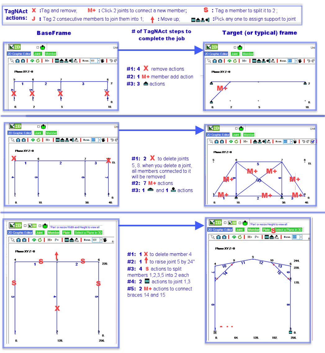
TagNAct: Select and Act on Structural Elements
TagNAct operates in real-time graphics and follows a WYSIWYG (What You See Is What You Get) approach. Every action’s result is displayed instantly. If the outcome isn’t desirable, simply click Undo  to revert it. In our system, TagNAct is used for both model and loading definitions.
How to Tag (Select):
Left-click a joint, any point along a member, or the centroid of a plate to tag it. Tagged elements turn red. Multiple elements can be tagged based on shared attributes.
How to Act:
Once elements are tagged, right-click to open a list of available actions. Choose an action, enter the required parameters, and execute it. The chosen action - whether geometric or loading - will apply to the tagged elements, and the display will refresh automatically.
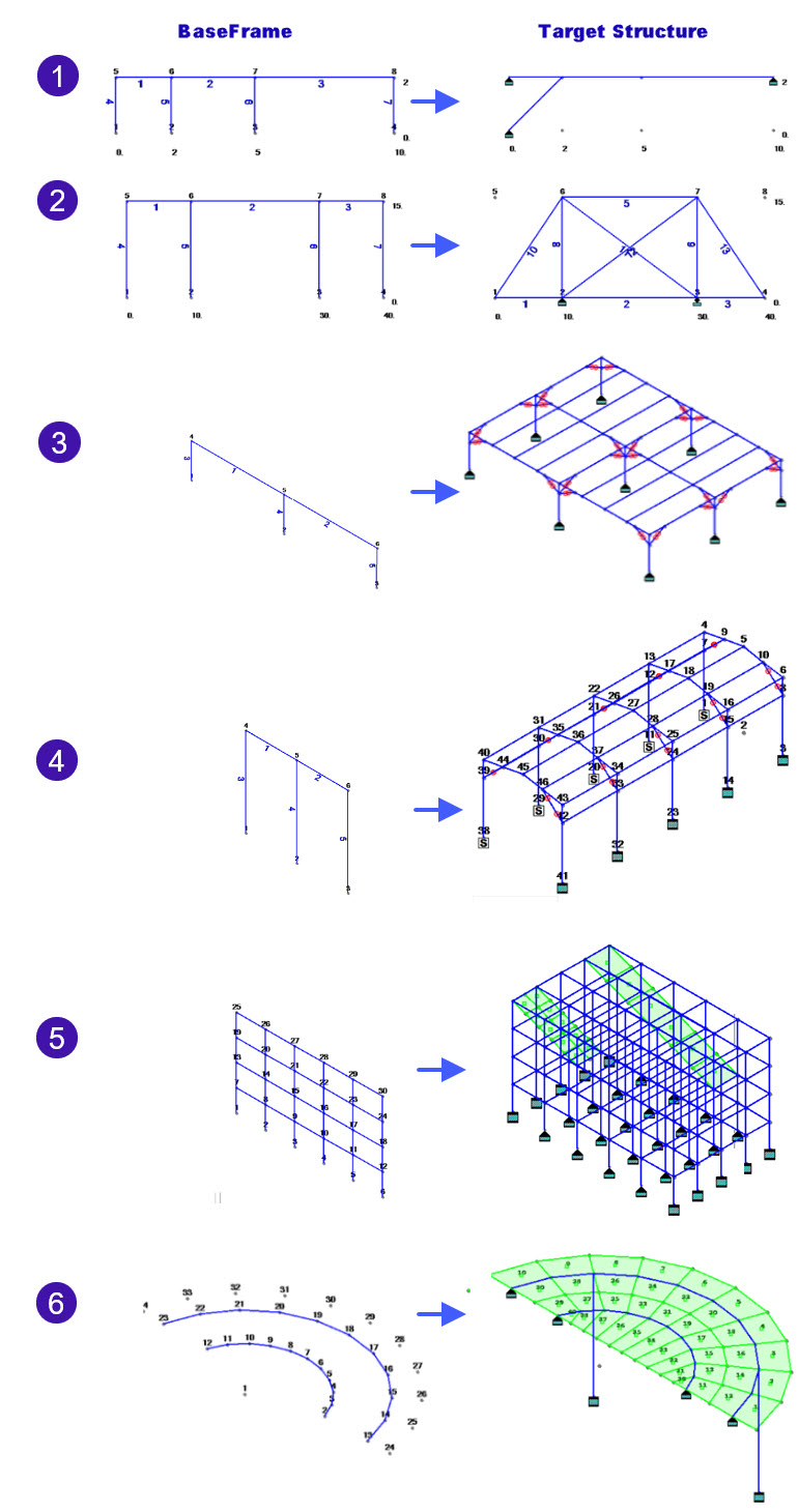
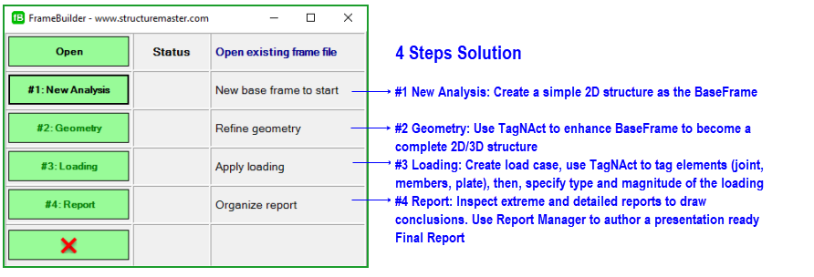
#1 Start a New Analysis: Create a BaseFrame
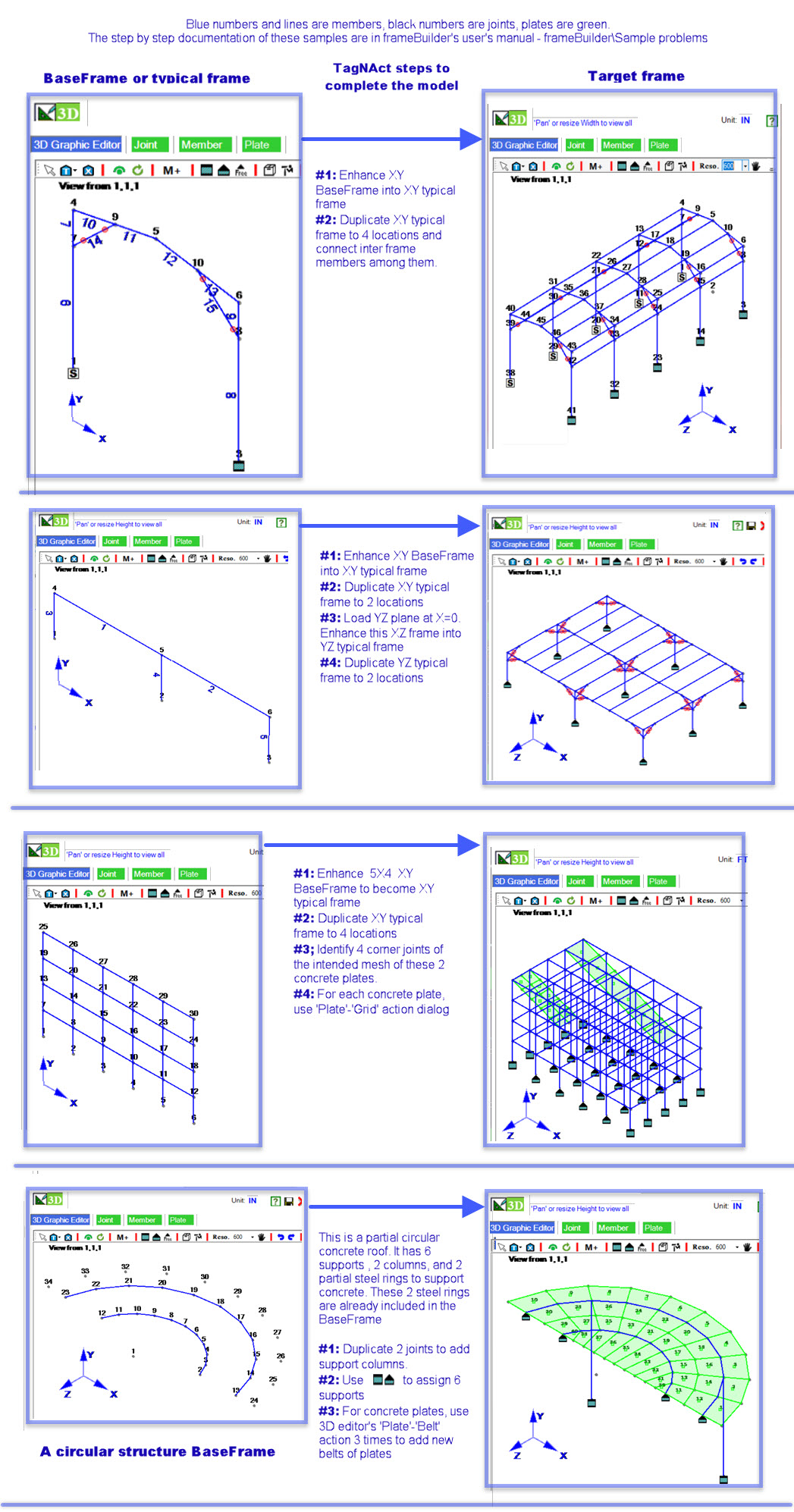
Every model begins with a simple 2D sketch called a BaseFrame. Below are six sample BaseFrames and their target structures. Cases 1–5: Rectangular grids in the XY plane (common in most structures). Case 6: Circular BaseFrame in the XZ plane.
Building a BaseFrame is a guided 3-step process:
1) Select analysis type - Choose 2D or 3D.
2) Choose geometry shape - rectangular, circular, or elliptical.
3) key coordinates for the BaseFrame - Specify the intersection coordinates of the connecting members.
Tip: With TagNAct, any BaseFrame - regardless of shape - can be modified quickly and efficiently.
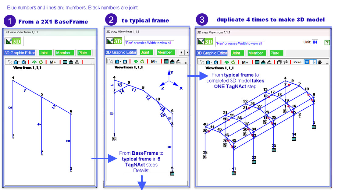
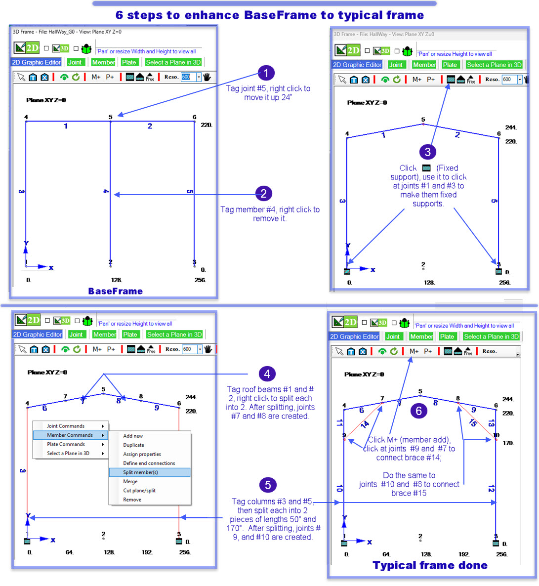
#2 Geometry: Enhance the BaseFrame
After the BaseFrame is defined, use TagNAct geometry actions to complete the model. Available actions are: Add New, Connect, Duplicate, Remove, Move, Merge, Spilt, Join, Cut, Assign Support, Add Grid, Add Plates. The bolded actions above are demonstrated in the following two examples:
Enhancing 2D models and
Enhancing 3D models via duplication.
In most cases, TagNAct allows you to complete the geometry in under an hour.
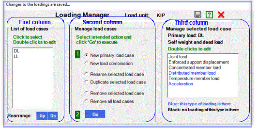
#3 Loading: Define and Apply Load Cases
The Loading Manager dialog box
is used to manage load cases and load combinations. Once a load case is created, use TagNAct to assign loadings to it.
Steps to assign loadings:
1) Tag elements — select joints or members that will receive loads.
2) Choose loading type: Select from: Joint loads, Enforced support displacement loads, Concentrated member loads, Distributed member loads, Temperature member loads, and self-weight.
3) Apply values — In the TagNAct dialog, enter the magnitude, direction, and any required conditions.
For detailed step-by-step instructions, view 'Step 5: Apply Loadings' in our Video Training Guide .
#4 Report: Authorizing a Presentation-Ready Final Report
Once the geometry is defined, loads are applied, and target load cases are selected, frameBuilder generates a text report. The opening page presents the Extreme Values of the selected load cases, followed by the Detailed Results of Each Load Case. Depending on the complexity of the structure, the report may span tens, hundreds, or even thousands of pages. However, the first page always provides a quick overview of the overall structural response.
After generating the report, further investigation is required to validate the results and draw conclusions. The Text Report Viewer enables easy navigation through the report using its Table of Contents. Video: Navigate and Investigate results through Detail Report
Summary Report:
Once you have validated the computer-generated results, it’s time to prepare the Summary Report. To do this, open the Summary Report Template and fill in key information, such as: Owner, Objective, Geometry, Loadings, Conclusion, Performed by… You can also insert graphics into the Summary Report to support your findings.
When the Summary Report is complete, the Final Report is ready. It consists of: Summary Report, Extreme Values Report, and Detailed Report. Video:
How to prepare the Final Report
End
 Back
Back